This post isn't attempting to present new research or a new device—that work has already been done, a la Bishop Fox. While an overall design was created, and many others have discussed building such a device, doing so can prove to be challenging. This post will provide you with all that is needed to fully construct a low-frequency (LF) card cloner, including printable drill templates, PC board (PCB) manufacturing files, and updated microcontroller code. All that's needed is your time and a basic set of tools.
Background
For the unfamiliar, the card cloner utilizes a long-range card reader, the same model seen on parking garage entrances and secured facilities, to gather the card ID and facility code of LF 125kHz proximity cards from unwitting targets. The device may be concealed within a backpack, messenger bag, or other concealment method of your choosing. The listed read range is a maximum 29 inches, which is dependent on credential type, operating voltage, and proximity to ferrous and non-ferrous metals.
Local power is provided by multiple AA batteries. Additional circuitry is installed to collect the card data and store it on a microSD card. This information can then be used to clone the data to a writable 125kHz card.
Upgrades
While the Bishop Fox design is great, we found that a few enhancements made it more user friendly. Additionally, an alternate display was chosen and the Arduino code was modified to utilize the stock SD card library. Enhancements include:
| Higher Operating Voltage | The maximum read range of the reader is dependent on the supply voltage. The battery quantity was increased to 16 to achieve a 24VDC supply. |
| External Power Switch | In order to conserve battery life, the reader shouldn’t run any longer than it needs to, but removing the cover to power up is cumbersome and could blow our cover. A rear-mounted power switch was added for easy blind location and activation. |
| Arduino SD Library | The original design utilized the SDfat library and a specific version of the Arduino IDE. This requirement made setup more difficult than it needed to be. The code was rewritten to take advantage of the stock library. |
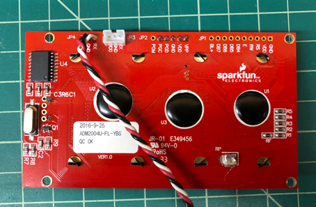
| LCD Display | In lieu of the display sourced from Amazon, which could become unavailable, an alternate display was chosen from Sparkfun. |
| Beeper Control Switch | So as to not draw attention to our activities, disabling the beeper would be ideal. While there are DIP switches on the reader control board, they are inconvenient for quick adjustment. A switch was added to the Arduino board for this purpose. |
Bill of Materials
Following is the bill of materials needed to build the cloner. At the time of writing, the PCBs were custom made. Not included are the light box, developer, and etching solution for production. A third-party fabricator may be considered at a future date, once a pluggable version for easy swap between reader types is designed. Additionally, the ability to drill >1mm holes for the through-hole components will be required.
| Qty | Comp | Manuf | Model | Description |
| 1 | | Amazon | B00AFY2S56 | Arduino Micro |
| 1 | | Amazon | B000W608FO | 2GB MicroSD Card |
| 4 | | Amazon | B01461P5V2 | M3x10 Standoff |
| 8 | | Amazon | B017NBZK7G | M3x8 Cap Head Screw |
| 2 | | Amazon | B01N1WDUK0 | M2x8 Cap Head Screw (assortment) |
| 2 | | Amazon | B01N1WDUK0 | M2 Nut (assortment) |
| 1 | VR1 | Mouser | 512-LM317LZ | Voltage Regulator |
| 1 | R1 | Mouser | 270-270-RC | Resistor, 270 |
| 1 | R2 | Mouser | 270-2K-RC | Resistor, 2K |
| 1 | C1 | Mouser | 667-ECA-1HM101 | 100uF Electrolytic Capacitor |
| 2 | | Mouser | 12BH381A-GR | 8 AA Battery Holder |
| 1 | | Mouser | 485-1116 | Board Edge Mounting Kit |
| 1 | TB1 | Mouser | 651-1729128 | 2P Terminal Block |
| 1 | TB2 | Mouser | 651-1729199 | 9P Terminal Block |
| 1 | | Mouser | 534-2504 | 6-32X3/4 Thumbscrew |
| 1 | S1 | Mouser | 655-1825232-1 | Slide Switch |
| 1 | S2 | Mouser | 633-MS12AFW01 | Slide Switch |
| 1 | | Mouser | 571-5-826629-0 | 50P Single Row Header |
| 1 | | Mouser | 590-630 | Copper Clad PC Board |
| 1 | | Sparkfun | LCD-09568 | Serial Enabled LCD Panel 4X20 |
| 1 | | Sparkfun | DEV-13743 | MicroSD Card Breakout Board |
| 1 | | | | Misc. Wire |
| 1 | | | | 1/8in Foam Pad (Battery Retention) |
Production
We aren't going to cover all facets of production here, because templates and files are provided at the end of the post. We will, however, cover some highlights related to reader modification.
A few plastic structures and a coil adhesive will need to be removed from the reader base. This can be done with a hacksaw blade laid flat on the surface, but an oscillating cutter will speed up the process. The adhesive can be scored with a razor knife and pried loose with a screwdriver.
[caption id="attachment_15110" align="aligncenter" width="656"]
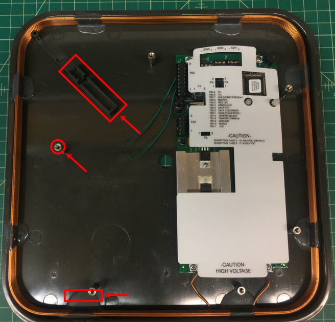
Figure 1 - Reader Base Support & Adhesive Removal[/caption]
Next, in order to control the beeper with an external switch, the circuit board will require a minor modification. One side of the piezo will need to be interrupted and routed through the switch, which will entail de-soldering the antenna coil from the control board in order to fully remove and access the bottom of the board. De-solder the piezo, rotate 45 degrees, re-solder one leg, and add two wires, as shown below.
[caption id="attachment_15111" align="aligncenter" width="647"]
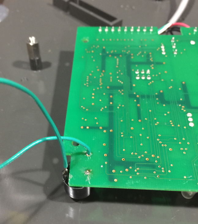
Figure 2 - Control Board Beeper Modification[/caption]
While the control board is removed, attach the drill template to the rear of the base, center punch the holes, and drill according to the size as indicated on the template. The control board can be reinstalled and the antenna coil can be re-soldered to the terminals.
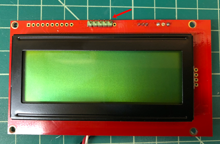
The display can then have wire soldered to the terminals and the mounting holes enlarged to 1/8-inch diameter. A header soldered to the PIC programming terminals is also recommended, as it enables easier re-flash of the firmware when needed.
Figure 3 - LCD Display Wiring & Programming Header
The fully assembled reader can be seen below. PCB fabrication will not be included here, as there are more than enough references on the Internets.
[caption id="attachment_15114" align="aligncenter" width="541"]
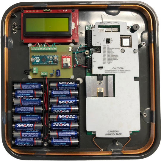
Figure 4 - Assembled Card Cloner Base[/caption]
Operation
Regarding the microSD card, the maximum size is 2GB. Formatting (MS-DOS) should be done via the SD Formatter from the SD Association for best results, which can be found at: https://www.sdcard.org/downloads/formatter_4/index.html. The card must also contain the file 'cards.txt'.
As with the Bishop Fox design, the Arduino code will check for card initialization and the presence of 'cards.txt'. The boot process will indicate both valid and invalid conditions.
[caption id="attachment_15115" align="aligncenter" width="474"]
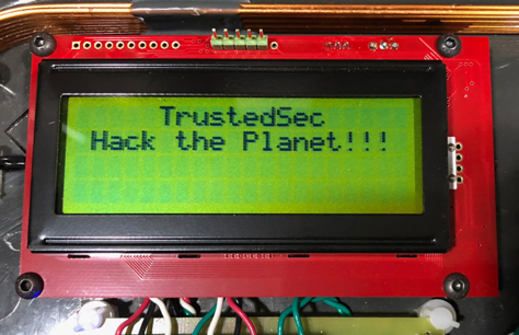
Figure 5 - Initial Boot Splash Screen[/caption]
[caption id="attachment_15116" align="aligncenter" width="481"]
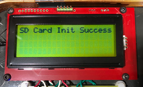
Figure 6 - Boot Confirmation of SD Card Initialization[/caption]
[caption id="attachment_15117" align="aligncenter" width="474"]
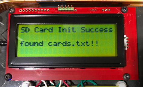
Figure 7 - Boot Confirmation of 'cards.txt'[/caption]
[caption id="attachment_15118" align="aligncenter" width="474"]
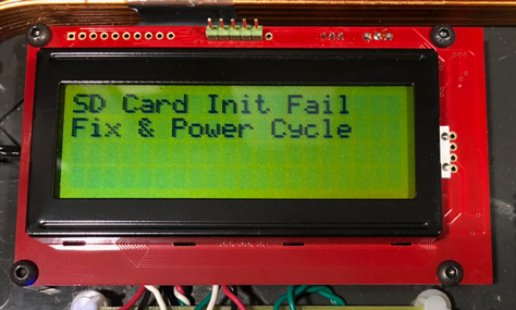
Figure 8 - Boot SD Card Initialization Failure[/caption]
[caption id="attachment_15119" align="aligncenter" width="474"]
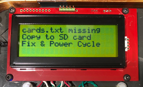
Figure 9 - Boot 'cards.txt' Not Found[/caption]
The display will note the last card the reader captured. All cards captured will be appended to the 'cards.txt' file on the microSD card. Data can be retrieved from the 'cards.txt' file when inserted into a computer.
[caption id="attachment_15120" align="aligncenter" width="477"]
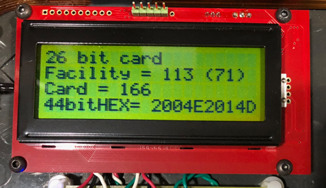
Figure 10 - Display of Last Card Read[/caption]
Drill Templates/PC Board Layout/Arduino Code
Download
here and
here.
Bonus!
What's better than carrying around a cloner to skim unsuspecting cards? One that you can install in the reader and let it do the dirty work for you!
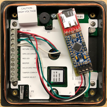
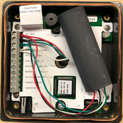
Based on the work above, we created an embeddable version that can be installed within the reader itself. It is fully powered from the reader line and sits in parallel with the data signal. It easily fits inside an HID ProxPro and can reside within the back box of a switch plate reader, like the HID Thinline II.
The same microSD recording method of all captured cards will be utilized in this design as well. Features a terminal block so as to not damage the reader conductors and can accept pigtails or the reader's direct wiring. Since there is no display, two LEDs on the rear indicate SD card initialization and the presence of 'cards.txt'. PCB layout and Arduino code are included below.
[caption id="attachment_15121" align="aligncenter" width="602"]
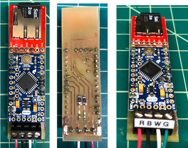
Figure 10 - Embeddable Card Cloner[/caption]
Figure 10 - Embeddable Cloner Installed Inside HID ProxPro
Bill of Materials
Following is the bill of materials needed to build the embeddable cloner. Most components are surface mount, with through-holes for the terminal block, SD card interface, and jumpers.
Conclusion
Hopefully this provides an easier path to constructing your own LF card cloner. Stay tuned for a modular version of the custom PCB that can be plugged/unplugged from the various reader types: HID Proximity, Indala Proximity, HID iClass, etc.
| Qty | Comp | Manuf | Model | Description |
| 1 | | Adafruit | 2378 | Arduino Pro Mini |
| 1 | | Amazon | B000W608FO | 2GB MicroSD Card |
| 2 | D1/D2 | Mouser | 696-SML-1206GCTR1 | SMD LED, Grn |
| 2 | R1/R2 | Mouser | 603-RT1206FRE07270RL | SMD Resistor, 270 |
| 1 | TB1 | Mouser | 538-39357-0004 | 4P Terminal Block |
| 1 | | Mouser | 571-5-826629-0 | 50P Single Row Header |
| 1 | | Sparkfun | DEV-13743 | MicroSD Card Breakout Board |
| 1 | | | | Misc. Wire |