June 27, 2016
OBD-II Break-Out Box (DIY Edition)
Written by
Jason Ashton
Penetration Testing
Security Testing & Analysis
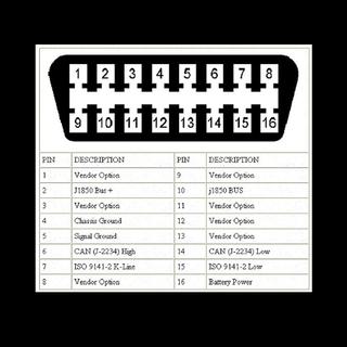
When assessing a vehicle's various electronic systems, the primary interface is the On-Board Diagnostics (OBD-II) port. This provides the connection to interface with the vehicle's CANBus, among others. The CANBus has been utilized in vehicles within the US since the 90s and has been mandatory since 2008.
While the CANBus, +12VDC, and Ground pins are in standard locations on the connector, other connection points like K-Line and manufacturer specific protocols can vary. Additionally, the two most common CANBus to computer interfaces, USB2CAN and Cantact, also utilize differing pins on their respective DB9 connectors to interface with the CANBus pins on the OBD-II port.
 Images of the assembled product are included below. Also included are .PDF drill templates and label for the box top/connections. As shown in the images, the box lid will be the bottom of the box to allow it to be removed once the label is applied.
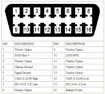
 OBD-II Pin-out

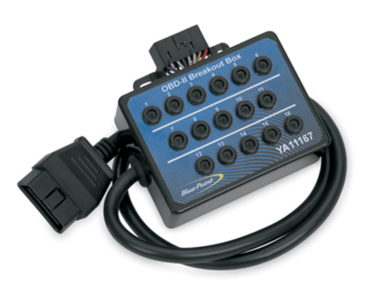 Typical Break-out Box
Images of the assembled product are included below. Also included are .PDF drill templates and label for the box top/connections. As shown in the images, the box lid will be the bottom of the box to allow it to be removed once the label is applied.

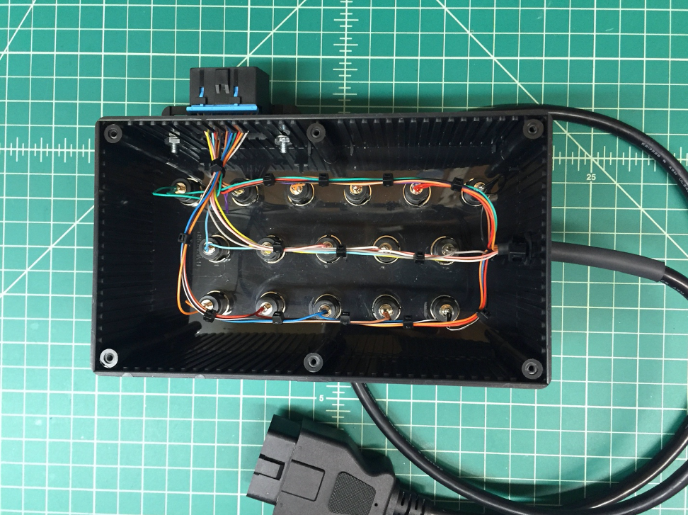 Box Inside

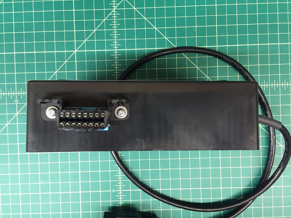 Box OBD-II Output Connector

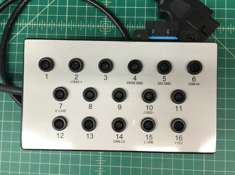 Box Top